M17 Rudder & Tiller Total Page Hits: 1808
Post Type: Technical/Project
Boat Part: Rudder
Date Modified: 02/11/2018 2:46 PM
Shared June 5, 2009 by Howard Audsley.
Every part of the boat is important, but the one piece of a sailboat you get intimate with more than any other is the rudder…..and it’s extension….the tiller. These are your main connection point to the boat. In a good wind, the boat will heel and the tiller literally comes alive in your hand. Perhaps more than anything else, this is a memorable part of the sailing experience.
Jerry Montgomery has written how the rudder on the M17 is an integral part of it’s ability to perform well in that’s is a large lifting foil. Not only that, but the M17, with it’s CB, is a variable draft boat. Most rudders on this type of boat are kickup, but the M17 has a unique one piece rudder that slides up and down on a 1/2 inch pintle rod.
As with everything else on a 25 to 30 year old boat, maintenance is required. In the case of Audasea, both the rudder and tiller needed replacement.
One of the first repair projects I attempted on this boat was the replacement of the tiller. The one that came with the boat was made of some exotic wood….perhaps even teak….but had a large crack in it. After looking it over….and realizing it’s importance…..I decided to replace it. Replacement wasn’t a big issue, the question is….replacement with what?
In one of the Pardey books, Larry is quoted as saying the tiller should be strong enough to block up on either end and stand on it in the middle. To those who followed Charlie Whipple’s saga of building a boat to sail round the world (Small Craft Advisor) only to lose the boat on the rocks within a week or so of her launching……I was struck by Charlie’s comment that when he first heard the crunch of the rocks, he ran to the cockpit only to find his tiller had snapped. No way to steer the boat and he lost her. Once again, Larry was right.
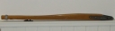
Back to finding a source of wood to make this strong tiller, I’m lucky in that my father has a really nice wood working shop, along with a large selection of hardwoods that he uses to make furniture and a variety of overbuilt, hell for stout wood working projects. My first choice for tiller stock would be black locust, or Osage orange, but lacking either of those, what I found was a ancient (meaning dry) piece of 2 x 4 quarter sawn white oak that was about 5 feet long and it had a natural curve to it that matched the existing tiller. The curve meant it was scrap that wouldn’t be used for most wood working projects, but perfect for my tiller. It was cleaned up and planed down to just over 1 1/2 inches in thickness. I then laid the old tiller on top of it, traced out the shape and cut it out on a band saw. That left me with the basic two dimension shape of my tiller, but the geometry of this was a bit more complicated, in that it tapers in two directions (looking down from above). See the attached picture that contains the dimensions I found.
To taper the tiller evenly from 1 1/2 inches at the rudder to 1 inch at the front took some thought. What I did was to put 4 marks on the tiller, then run it through a planer (jointer), starting at the front mark (first mark about a foot from the left)……lowering the tiller onto the jointer on the first mark, then passing as you are viewing it from right to left, to the handle end. Turn it over and do the other side. Move up to the next mark and do it again….running it from the mark to the handle end. Repeat this 4 times. With the jointer set to take off 1/16 th inch with each pass, The handle end had half an inch total removed and the taper was set. Lastly, I hit the edges with a 1/4″ roundover bit on a router and it was ready to sand and finish. In this case, 7 coats of Interlux Goldspar, a polyurethane from Interlux.
I’m happy to report it passed Larry’s stress test, and has held up really well.
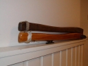
Decoration aside, the turk’s head knot at the handle also has a functional use, as it provides a register for your hand without having to look at the tiller. The cleat on the underside is used with a piece of line tied to coaming cleats and serves as a tiller tamer. This tiller is 42 inches long, but is 1/2″ too long, as it barely passes through the split backstay as the tiller pivots up. Other than that, it’s a great length to sit anywhere in the cockpit and steer. I hardly ever use the hiking stick….mostly out of personal preference.
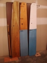
Next up was the rudder….represented to be solid mahogany. It turns out it is!
Basic stock would be a 6′ x 1′ x 1.5 inch solid wood (either one piece or a variety of laminated strips). From that, it’s cut out to it’s final shape. As it’s not easy to find a 12″ (actual 12 inches) block of mahogany, the rough stock is made by gluing some strips on the leading edge. In the case of my original rudder, that front lamination had fallen off, so it was just a square leading edge. I took the liberty of rounding that over and got a couple years out of it, before realizing the rudder also was bent….being nearly 1 inch out of line at the bottom. Let go of the tiller and she always turned to one side. Beyond that, the aft edge was no longer sharp, nor was it the same width. At speed, it would hum and vibrate something fierce. All things considered, it was time for replacement. I could make one, but before I went that far, I called Bob at the Montgomery factory and was able to purchase one at a reasonable cost. Problem solved….except it needed to have holes drilled for the hardware.
Smack in the middle of all this, I decided I wanted to build a self steering wind vane, and the design I chose meant drastic surgery on the tiller….something I didn’t want to do to a gorgeous piece of mahogany just to satisfy my curiosity, so it was back to building.
For the experimental wind vane rudder, I wanted cheap and easy, so I glued together two 1′ x 6′ strips of 3/4″ marine plywood (there was a reason for this….but this is not the time or place for that). But to cut it out, I needed the dimensions. I’d never paid much attention to the rudder before, but it’s a piece of work….complicated by a number of factors, not to mention the transom apparently has a bit of rake to it (about 4 degrees).
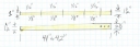
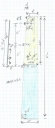
But as to the rudder, if you want to make one, here are the dimensions (taken from the new rudder…..the new and old differ slightly).
If you look closely, you notice the rudder tapers from 12 inches at the base to 10 3/4 inches at the waterline, then up to 8 inches at the head. Tiller tilts up, so it pivots on a hole, but rests on a 1/2 inch ledge. Butt of the tiller is the same width as the rudder head. Other than getting the foil shaped right, building this is not all that difficult. I used a NACA 0012 foil shape, and it worked fine.
To enable the rudder to raise and lower, a line attaches to a deadeye on the transom and runs through a lifting hole, then back to a cleat…also on the transom. You can slide the entire rudder up a little over a foot, cleat it off….and still have a fully functional rudder. Aside from being a “spade” type rudder, which itself is vulnerable to hitting stuff, the rudder exerts a considerable amount of leverage on the rudder pin during a grounding. These are often bent, so having a spare is a good idea. Once the pin is bent, sliding is hard at best, but more likely impossible.
As a side note to the rudder pin, when installing gudgeons on a new rudder, one of the more complicated tasks is to get them all lined up straight. The “hinges” are similar, but not exactly the same, so you really can’t pre-drill your exact holes. Better way is to put them about where you want them, then insert the 1/2″ rod and make sure it slides easily, then drill the holes with the pin still in place. Even doing this, it may get out of line to the point it binds vs. sliding easily. Not only that, but any variation is going to cause problems, so if you remove the hardware from the rudder, mark them 1, 2 and 3….A, B, C, whatever, and mark them to one side so you put them back exactly as you took them off. Same position and not flipped over. Otherwise, they may not align to a straight rudder pin. When drilling, I put one hole on the end pieces, get it all working straight, then drill one hole for the middle one. If it stays all lined up, I’ll drill and install the remaining 3 bolts. All important, as if the rudder pin binds, the rudder won’t raise and lower easily.
With basic tools, making a new rudder pin is easier than you might think. I’m now on my 2nd or 3rd replacement pin, so I keep a supply of 1/2″ 316 stainless stock, which I can cutoff with a jig saw and holes for the clip pins with a drill press. The secret to drilling stainless is good bits and go slow. The slowest setting the drill press has and keep the bit wet with cutting oil or water. 316 stainless is softer and easier to bend than 304, but is also easier to machine, and is more corrosion resistant. I’ve heard Jerry suggest aluminum bronze for this, but have not tried it. Please note, newer boats have a different pin arrangement. The bottom is machined to fit in a smaller gudgeon. If you have that, you are on your own.
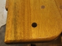
As the rudder is wood, holes are best drilled out oversized and backfilled with epoxy. That is the 6 holes for the rudder brackets and one hole for the tiller bolt. The oversize in my case is 1/2″ holes for 1/4″ bolts. Leaves 1/8″ margin around the bolt and “room to roam”, meaning room to wander around a bit to get the alignment right. See above.
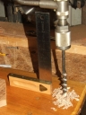
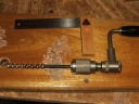
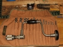
Some pictures on how I do it are attached.
For some time now I’ve been collecting and using a variety of hand tools (saws, planes, drills), and find it remarkable how well they work. The original cordless drill…..along with a set of Russell Jennings double twist bits. Cuts perfect holes with no tear out and cuts them fast…
Backfilling with epoxy does double duty for these, as a plain hole in the wood will allow moisture in and rot will start, and once that happens, the bolts holding the bracket on start to pinch the wood in as you keep tightening them when they work lose from rot. This is especially important for the bottom bracket, as it operates below the water line. Not only does it limit moisture, but epoxy acts as a spacer bushing. At the tiller end, look close and you will see it’s only one bolt that holds your tiller onto the rudder head. Don’t want that to fail!
If you have questions…..feel free to ask.