M15 Mount and Ladder Installation Total Page Hits: 1447
Post Type: Technical/Project
Boat Part: Transom
Date Modified: 05/30/2016 4:48 PM
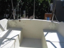
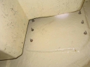
I replaced the factory motor mount on my 1982 M15 when I bought my 2 HP regular shaft Honda outboard. I planned on replacing the motor mount and installing a stern pulpit and boarding ladder, so I first had to install two 4" access ports, one on each side of the cockpit transom, above the bench seats. I did this in 1997 so my memory has faded on the details, but to install the ports I cut a 4 1/2" hole and bolted the flange to the bulkhead. This helped with the installation of the mount, pulpit, and ladder, but it still takes contortions to reach all the fittings. There are no cracks or checking from the holes after 11 years, so the structural strength of the boat was apparently not significantly compromised.
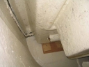
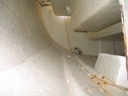
An important added benefit is that you can see what you are doing. It is not apparent from the outside, but the transom looks like it is constructed with a glassed-in balsa support that does not extend all the way to the top. The top 3 1/2" are fiberglass that is about 3/16" thick, below which is the reinforced transom that is about 7/8" thick. It does not seem like a good idea to mount anything weighty on the thin part of the transom. I could not verify that there was any plywood inside the thick part of the transom, which was a surprise. It looked like there are three thick panels in the transom, one on each side for the motor mount and ladder, and a center panel for the rudder. I do not know if all three panels are constructed the same way, but I suspect they were. Jerry Montgomery has assured me that the transom is plenty strong enough for a motor mount and boarding ladder.
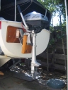
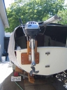
For the motor mount, I did not want to drill new mounting holes in the transom and plug old holes, so I used the existing holes to bolt on a mounting plate, and fastened the motor mount to the mounting plate.
First, figure out where to place the new mount. This will depend on the geometry of the new mount. I placed my new mount 14.25" o/c from the rudder pintle such that the top of the block holding the motor was about 7" below the top of the transom when the motor was lowered into the water.
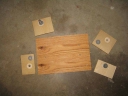
Prepare a mounting plate. I used 1"X10"X15" mahogany. Recess and install the motor mount bolts and washers from the inside of the board, using the new mount as a template. Finish with Cetol and dry. I sealed the bolt heads with epoxy so the bolts would not turn if I ever have to remove the nuts. Check that the holes line up with the transom holes and epoxy the transom holes, re-drill, apply a bead of sealant between the transom and mounting plate, and bolt together. I used Boatlife Life Caulk polysulfide sealant. You may choose to install backup plates inside the hull. I did not. Bolt the motor mount to the mount plate.
The engine mounting block that came with my new mount was 2" plywood, which soon failed. I replaced it with a 2X8X10.5" solid block that is starting to show some wear, but still looks better that the original. The new models have a polypropylene engine block. I adjusted the height dimensions of the replacement motor block to get the best propeller depth. The bottom of the motor mount drags in the water while motoring, but I do not see this as a problem since I do not motor for long distances. Make sure the motor mounting block is high enough to permit tightening the motor screws.
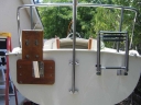
I also installed the stern pulpit in 1997, and can recall no major problems doing it; the pulpit mounts above the transom had 3 equally spaced holes on a rounded base. Two of the holes accepted bolts and nuts; the third was too close to the side wall so it had to be attached with a screw.
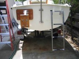
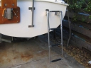
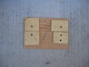
Installing the boarding ladder was done in June 2008. I did not have an assistant small enough to crawl under the cockpit, so I modified the method described in the old Montgomery Newsletter (see bottom of this page). I prepared a backup plate of 1/2" oak plywood scrap, about 7"X11". Drill 1/4" holes using the ladder as a template. Made nut holders from 1/2" ply by drilling 7/16" holes inside of an 11/4" indent made with a Forstner Bit to seat the washer. Pound in the nut with a hammer and epoxy to the board, keeping a bolt in the nut to protect the threads. Place a washer in the indent and glue and screw the assembly to the backing board. Inspect the nut to insure it is firmly seated and the threads are clear. Take special care that the nuts are firmly held, the nut threads are free of any debris that may jamb the bolts, and the bolt threads are not marred. Thread a bolt in and out a couple of times to loosen the nutlock. This is very important, because if the nuts slip or the bolts jamb, you will have to crawl under the cockpit to fix things.
I drilled 1/4" holes in the transom for the motor mount with the upper starboard hole being about 6" below the lip and 8" from the outer edge of the boat. Take care to drill the holes perpendicular to the transom face or the bolts will not align correctly. Under the cockpit, there is about 2 1/2" between the transom and the cockpit locker for the two outer holes. The inner holes have unlimited room inside. Epoxy the holes and re-drill.
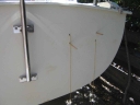
Cut 16' of line that is thin enough to fit through the nuts yet strong enough to pull on. Pass each end through two diagonally opposed holes and fish back to the cockpit. Thread through the appropriate nuts in the backup plate and securely tie to form a loop. Pull both parts of the line from outside the transom, pulling the backup plate into position inside the transom. The backup plate may take some nudging with a boat hook to pass by some of the barriers under the cockpit. I found two 1/4" dowels sharpened on one end to be helpful in aligning the nuts to the bolt holes.
Align the ladder to the transom and loosely thread in two bolts. Cut the line and push the cut ends into the boat. Loosely insert the remaining two bolts, apply an appropriate sealant such as 5200 to the ladder mounting plates, carefully tighten (do not over tighten and strip nuts from holders) and let set overnight before applying weight to ladder.
Congratulate yourself and go sailing.
(2) Screw in ABS Deck Plate 4" WM# 7788508 $12.99 eaFulton ADJ Outboard Bracket to 10 HP WM# 380321 $162.99 (current model)Westline boarding ladder, 4 step, Part No R-1185, $100.(4) 1/4 -20X2" ss bolts @ $1.25 each4 ss washers @ $0.20 each (4) 1/4-20 ss locknuts @ $0.30 each
Story and Photos by Robert Becker